| |
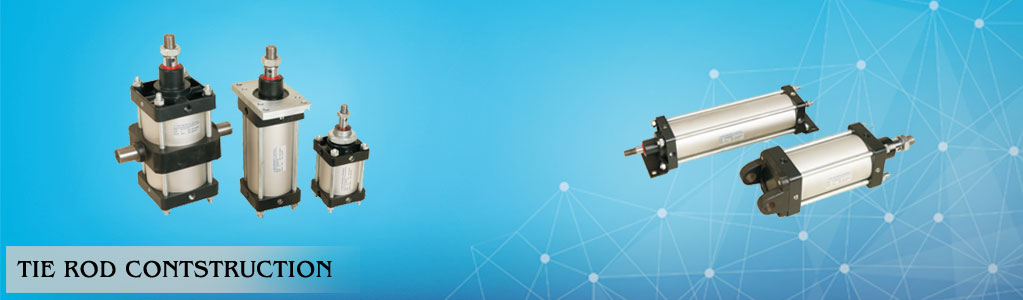
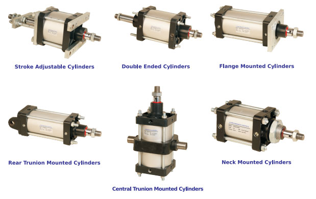
θ1 ½" -θ14" Bore Air Cylinders
• Sizes available 1 ½", 2", 2¼", 2½" 3 and 4" bore diameter (Medium bore) and 5",6", 8",10", 12" and 14" bore diameter. (Large Bore)
• Suitable for a wide range of applications.
• Available in all types of mountings and attachments.
• Single, Double acting, Magnetic, Double Ended,
Tandem, Telescopic.
• Max stroke lengths upto 2000 mm.
 |
 |
| |
| Technical Characteristics |
| • |
Media : Air |
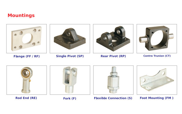
| • |
Mountings & Accessories |
| • |
Seals : Nitrile, Viton on request |
| • |
Temperature : 0°c to 80°c (for Nitrile Seals) |
| • |
Piston : Up to 4" Aluminium & from 5" to 14" cast iron. |
| • |
Pressure : 0.5 to 10.2 kgf/cm2, high pressure on request. |
| • |
Piston rod : En-8 (ground & Hard Chrome Plated), SS304 on request |
| • |
End Covers : Up to 4" Aluminium die Casted & powder coated. From 5" to 14" close grain cast iron & powder coated. |
| • |
Cylinder Barrel : Upto 4" Dia, Aluminium, M.S.
(Honed & Hard Chrome Plated) From 5" dia.
To 14" dia . MS (Honed & Hard Chrome Plated) Powder Coated on request |
| |
|
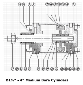
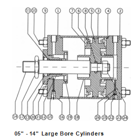
| Part List |
| No. |
Description |
Qty. |
| 01 |
Front cover |
1 |
| 02 |
Rear cover |
1 |
| 03 |
Tube |
1 |
| 04 |
'0' ring for cover |
2 |
| 05 |
Wear ring |
1 |
| 06 |
'U' cup seal for piston |
2 |
| 07 |
Piston |
2 |
| 08 |
Tie rod nut |
8 |
| 09 |
Tie rod |
4 |
| 11 |
'U' cup for piston rod seal |
1 |
| 12 |
Bush bearing |
1 |
| 13 |
Wiper Seal |
1 |
| 14 |
Piston rod |
1 |
| 15 |
'0' ring for bleed screw |
2 |
| 16 |
Bleed Screw |
2 |
| 17 |
Lock nut |
2 |
| 18 |
Cap (for Medium Bore cylinders) |
2 |
| 19 |
Cushioning boss (for Large Bore cylinders) |
2 |
| 20 |
Cushioning Seal |
2 |
| 21 |
Sleeve (for Medium Bore cylinders) |
2 |
| 22 |
bush (for Large Bore cylinders) |
2 |
| 23 |
'0' ring for Sleeve
(for Medium Bore cylinders) |
2 |
| 24 |
'0' ring bush (for Large Bore |
2 |
| 25 |
Check Screw |
2 |
| 26 |
'0' ring for check screw |
2 |
| 27 |
Piston rod nut |
1 |
| 28 |
Spring |
2 |
| 29 |
Ball |
2 |
|
| |
|
 |
| |
|
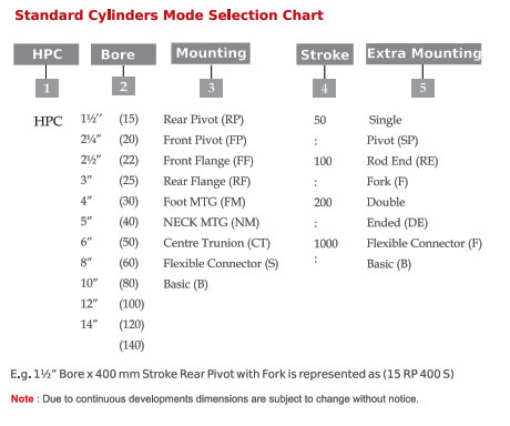
| Note : |
| To decide cylinder bore size : |
| • Establish force required and working pressure available. |
| • Select working pressure on top of the chart. |
| • Select force required by reading down from selected working pressure. |
| • Read Out Cylinder bore size on left of the chart. |
| |
| Example : |
| • If it is established that the force required is 150kg and working pressure available is 7 bar, above chart will lead you to select 7 ¼" bore cylinder. |
| |
|
| |
 |
| |
 |
|